MODERN PASSIVE ACOUSTIC-SEISMIC MONITORING SYSTEM
The 5DQM Concept
Ernst D. Rode/Stephen Marinello
Introduction/Abstract
Passive Monitoring Technologies are those that detect and compile ‘background noise’ emissions across a wide span of wavelengths and do not generate a signal themselves. They depend on the cognitive interpretation of all background noise and are, therefore, broadband communication/detection systems. They require very highly sensitive sensory perception capability and very advanced signal processing, analysis and interpretation. They are used to detect and monitor, which means they provide information about the localization and the nature of target and its contemporary and predictive behavior across time.
Passive Monitoring Technologies may operate in the Acoustic-seismic or electromagnetic domain.
Passive Background Monitoring Technologies were recently applied mainly in the defense industry [10]. The Quantum Leap in Passive Background Monitoring Technologies and in passive acoustic-seismic monitoring technologies is the recent revolution in Cognitive Data Management Systems (CDMS) based on Deep Learning (DL) algorithm [13] and the application of artificial neural Networks (ANN) [9];[10].
1. Background and History
Passive Monitoring or passive observation has been known since the beginning of organic life on earth:
The observation and interpretation of dynamic changes in the environment is the pre-condition for successful survival – and success.
In the course of the technical evolution human beings lost many of their “natural senses” or the ability to rely on them. On the other hand they developed numerous technical aids and instruments in order to enhance their senses, such as X-Ray, Radar, Sonar and Reflection Seismic systems and also optical and thermal sensing devices.
Most of such devices are of active nature and were developed for advanced applications for the defense, medical and resource industry.
Active systems apply a technical controlled signal source using the principles of reflection, refraction or reaction at the structure or at the target which is to be observed. The information results of such systems are mostly one dimensional and equivalent in kind to the energy emitted from the source. Therefore, the information results are limited. They are mostly applied to locate objects.
As noted, Passive Monitoring Technologies depend on the cognitive interpretation of any kind of background noise and are broadband communication systems. They use a very highly sensitive sensory capability and require a very advanced process of signal analysis and interpretation. They are mostly used to detect and provide information about the localization and the nature of an object and its contemporary behavior: Detection means localization and identification. Monitoring provides continuous localization and characterization through time.
The “object” or “the subject of detection” is sometimes defined as a “Technical Dynamic System” (TDS)[1]
The “Information Carrier” which is used by Passive Monitoring Technologies is based on the “Dynamics” of phenomena and it can be of acoustic, electromagnetic, gravity or chemical nature. (In earth dynamics this is a coupled quadruple).
The 5DQM concept was designed to develop technologies for the recognition of geodynamic phenomena based on the continuous acquisition and interpretation of non-structured “data” which are created from acoustic-seismic signals generated by the omnipresent acoustic-seismic and electromagnetic background noise.
The technical goal of 5DQM Technology is: Controlling Technical Dynamic Processes
- control of technical subsurface engineering processes – to optimize the performance of the technical systems
- Mechanistic Acoustic-Seismic Hazard Assessment to predict man-made and natural Hazards – to initialize early warning procedures and minimize collateral damages
Explanation:
E (1): Technical Subsurface Engineering Processes shall mean such as
- The control of fluid dynamics in Oil reservoirs to enhance oil recovery
- The control of petro-geothermal power generation to optimize Heat Exchanger Performance (HEP) and minimize the risk of induced seismicity
E (2): Mechanistic Acoustic-Seismic Hazard Assessment shall mean
- Control of artificial underground storages for Oil/Gas/CO2/N2/H2 and Nuclear Waste Deposits – Hydro Power Dams and Nuclear Power Plants.
- Early Assessment of Natural Hazards like Earth Quakes, Tsunamies, Avalanches, Landslides and after shock risk assessment.
2. Cognitive Data Management Systems and Artificial Intelligence
The Basic Idea of the 5DQM Concept is to use continuous monitoring of the acoustic-seismic background to retrieve and analyze information for the control of technical dynamic systems (TDS). This includes the identification and assessment of “technical” operating risk and “natural” hazards.
(In general the 5DQM information analysis refers to any kind of “background analysis”)
Explanation:
Any system control process is based on a signal history matching procedure which unveils an information – footprint.
We have to differentiate between “signal analysis” and “information analysis”[2].
The information analysis referred to in the 5DQM concept – the background noise analysis – requires “recognition” of a “signal composition” to “make a conclusion” about the – most probable -impact of this “composition” on a technical process.
This “recognition” and “conclusion” results in information based on which performance of the “system” can be managed and optimized.
The information analysis of a TDS in subsurface engineering activities is a semantic problem – the understanding and interpretation of “The Sound of Geology”.
The process to recognize, conclude and act requires something which we call “knowledge”, which is generated by the “experience” developed through continuous analysis: Knowledge provides for understanding of the probable behavior of the “System under Control” in near future.
Knowledge born from Experience can be described as the result of a “Deep Learning” process.
Machine Learning processes satisfy originally Cybernetic Processes (N.Wiener)[6] applied in machines which have learned to perform to control processes in one or more (x,y,z,t) dimensions – they do not satisfy the requirements of “Knowledge Accumulation” for Cognitive Data Management Systems”. It is the “Deep Learning Revolution”[3] and Big Data computing capabilities with Artificial Neural Networks (ANN) which enables us to accumulate the “Knowledge” which the System (CDMS) needs to control a TDS.
- Knowledge is stored information acquired by the (neural) network from its environment through a learning process and used to respond to the outside world[4]
- Knowledge requires that the system has the ability to store and remember (deep learning).
In the 5DQM monitoring and control process this knowledge has to be “learned by experience” from the behavior/response pattern of the system under control. This implies that the 5DQM monitor is able to recognize “behavior pattern” of the system.
Recognition requires the ability to store and remember and compare.
Cognitive Data Management Systems become “intelligent” when they have the ability to “render a decision” – in this case we are talking about “Artificial Intelligence”.
Remark:
- 1. The ability to replicate a cybernetic process – does not require intelligence – and does not fulfill the criteria of intelligence but those of machine learning.
- 2. Artificial Intelligence (AI) is based on “deep (machine) learning programs” as opposed to
Natural Intelligence (NI) which is based on “natural (human) learning programs”.
The difference between Natural Intelligence (NI) and Artificial Intelligence (AI) is only a semantic difference based on “Human Ethics”. A “Machine learning” Program becomes “Intelligent” (Artificial Intelligence) when it is allowed and able to have a “Guessing Space” and “Emotions” equivalent to “Natural Intelligence” in decision making processes.
The expression “Artificial Intelligence” is generic. In terms of Artificial Intelligence the operating center which creates “intelligent” processes is called an “Agent”:
CDMS in a passive monitoring and control unit (5DQM) is such an “Agent”.
CDMS – “Cognitive Data Management System” is the central operator in 5DQM monitoring and control system. The Intelligence of the “Agent” is based on the following attributes:
- CDMS is able to acquire, memorize and store data in a continuous forensic data base (FDB)
- CDMS is able to extract information from non-structured data
- CDMS is able to quantify and qualify information
- CDMS is able to recognize information
- CDMS is able to validate new information in opposite to previous information based on the content of the forensic data base (FDB)- Knowledge
- CDMS is able to remember the influence of control data on the monitored behavior of the system under control (Feedback Loop)- Knowledge
- CDMS is able to learn and generate rules (“Codex”) of behavior of dynamic systems
- CDMS is able to render decisions and make conclusions based on the lessons learned and the generated “Codex”
- CDMS is capable of QRT
QRT – The ability for “Quantification of Relation between Things”
Figure 2.1.: CDMS with FDB and QRT

Figure 2.1.: CDMS with FDB and QRT
FDB – Forensic Data Base – is an n-dimensional data memory (Event Space[5]) which is dynamically and continuously upgraded with an n-dimensional data stream starting from T0 which is the beginning of the individual monitoring subject history. FDB contains the beginning action model of the dynamic system under control (genotypes) which is continuously and iteratively upgraded by a “true model” learned by experience and serving as Knowledge Data Base for process data recognition (phenotypes).
Remark:
There is a bridge from Artificial Intelligence to Human Intelligence when the “Agent” has the following complementary attributes:
- Agent is able to create emotions
- Agent is able to recognize itself – (Rene’ Descartes “Cogito Ergo Sum” 1596-1650)
- Agent is able to reproduce itself
3. Creating Information for 5DQM Process Control and HAZARD Assessment
The purpose of a 5DQM passive monitoring system is the Process Control (ProCon) of a Technical Dynamic System (TDS).
Definition:
Process Control shall mean: The deterministic-numerical control of a “Technical Dynamic System” (TDS)
Cognitive Data Management Systems (CDMS) is the (intelligent) “Agent” for Process Control.
A good example of CDMS and an intelligent AGENT is a good tennis player: In the beginning of the match he knows nothing but he has already his experience about the behavior of the systems (TDS) and he has his technical skills. During the course of the match he is building up his FDB and his brain with its optical and acoustic sensors (perceptrons) is calculating the entropy of the system: – counterpart – bottom – ball – racket – speed
(Natural Intelligence).
The “Technical Dynamic System”[2] is the physical system under control. This physical system can possibly be described mathematically as a “Dynamic System”[6].
The dynamic behavior of the TDS depends on a number N of dynamic variables and a certain number K of a parameter. The behavior is initially described in a probability model. (Bayesian probability and Kolmogorov-Sinai Entropy)
The CDMS is recognizing the system behavior based on the initial probability model and generating the technical control feedback data for the TDS referring to the “Knowledge” stored in the FDB – either as a pre-defined model which is iteratively corrected, or as generated from an “innocent” learning process where the TDS itself serves as the “Teacher”.
The Function of “Knowledge Building”[9] and “Experience” is the convolution of initial behavior model and “True Behavior”. This Knowledge is stored in the “Forensic Data Base” (FDB) as “Knowledge” from which probability data are generated to technically control the TDS.
The incoming control data are generated by CDMS from unstructured data. It is obvious that these unstructured data – converted into structured data – carry the information which is needed to control the TDS – and at the beginning of the process the “information code” [4] is unknown.
For the TDS control we have to differentiate between two different problems:
- The behavior of the TDS under control is deterministic (pump station or nuclear reactor) - “KNOWN System”
- 2. The behavior of the TDS is probabilistic – (Geothermal Heat Exchanger in a rock matrix Fig.5.2. – or underground storage for produced or refined hydrocarbons or waste products)- “UNKNOWN System”
For problem (1) the CDMS (Agent) has a deterministic reaction model as complementary Knowledge Data Base to identify and create the control information. This model is weighted with a certain amount of uncertainty – the natural uncertainty of the feedback loop control system.
For problem (2) the CDMS has to learn the genetic structure of the information, based on a simulation model in an iterative process to generate the most probable – true – information to feed it into the control loop – inverse modeling [9].
In this case the TEACHER is the TDS itself.
Remark:
A major principle technical problem of the system is the transformation from Signals – into Data – and Data into Information.
In Problem (1) the relationship between Signal and Information may be widely known
In Problem(2) the relationship between Signal and Information is probably unknown or at least uncertain this applies not only to TDS but also to HAZARD monitoring and early warning systems where knowledge about input data and reaction model would also have to be learned and extracted out of the FDB.
The technical challenge for both cases is the performance capability of data acquisition and sensor (receiver or signal converter) components. – Such technical features shall not be discussed in this paper although they are very critical for the configuration of the CDMS.
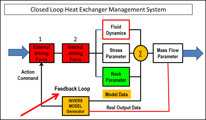
Figure 3.1.: Block diagram for inverse system modelling
Figure 3.1 shows a heat exchanger management control system for Mass Flow v.s. induced seismicity where the dynamic TDS parameters are unknown according to Problem (2). In this case the “System” is the Teacher for the CDMS. (Inverse Model learning).
Summary and conclusion:
Permanent Passive Monitoring Systems are the basic instruments to control the social economic development of the human community and its technical operations.
Permanent Monitoring Systems by nature have to be passive and they depend on the capability to handle “BIG DATA” and “Cognitive Data Management Systems” to convert large quantities of non-structured random data into information and a feedback tool.
The front end of a passive monitoring system is a technical receiver array which is always an analog device in the acoustic or electromagnetic domain and the outcome of the system is a control and steering tool for all kind of development processes based on the accumulation of information created by artificial intelligence.
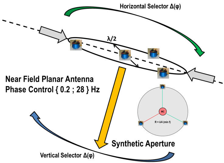
Figure 3.2: Passive monitoring front end device: Directional Acoustic Planar Antenna Array
- Permanent Passive Monitoring Systems have to be seen as an intelligent survival and control tool for any kind of dynamic systems
- Today essential for the control of political and social economic development but also essential for the control of all kind of production and logistic processes.
- A technical control and steering tool for the efficient exploitation of hydrocarbon reservoirs and all kind of natural resources
- A control tool for heat exchanger performance in Enhanced Geothermal Systems
- Earth Hazard Assessment and warning systems
- Enhanced security systems for intrusion control and terroristic acts.
4.1. State of the Art
There are fundamental ways in which the 5D Quantum Monitoring (5DQM) concept differs from conventional seismic surveys performed in the energy industry. The 5DQM system makes use of the continuous broad spectrum ‘background’ signal passing through the subsurface of the earth. The system continuously, passively, and noninvasively monitors the modifications or alterations in the signal form as it passes through the targeted volume; from baseline differences that exist at project initiation to the continuum of differentials that develop through time. Conventional 2D/3D/4D seismic monitoring methods generate a compressional source wave and detect the reflected waveforms and the differentials created in those waveforms at a single point in time.
While both concepts target definition of the reservoir, addressing structural form and the location of different fluids in the reservoir volume, these goals differ in basic nature in each system.
3D/4D Seismic Surveying: Reflection Seismology Defining the Reservoir
Conventional 3D seismic survey methods utilize multiple wave source generators, of various types, to initiate a compressional wave into the subsurface. These were originally oriented in a ‘line’; a linear array, generating what is now known as 2D surveys, or in multiple linear arrays (two or three) generating a 3D seismic survey. Reflections of the generated waves occur at formation layer boundaries existing in the subsurface lithology. These reflections are detected and logged at the surface by geophones/seismic sensors that focus on a narrowly defined range of frequencies. The character of the reflections are processed and analyzed to infer the depth and character of the formation interface; harder vs. softer rock, and the potential of hydrocarbons existing in a given formation by the damping effect of the fluid saturating the pore space. This is based on the effect of the density of the fluid; water being more dense than oil; gas being much less dense than both. This is why gas reservoir accumulations can generally be seen more easily, as ‘bright spots’ in generated representations.
The improvement in execution, processing and analysis has made 3D seismic a very useful exploration tool, reducing the risk associated with targeting and developing a given reservoir. However, as an exploratory tool, it gives only a beginning point of reference for the reservoir. As a reservoir is produced, fluids migrate, stresses change, and these changes in the subsurface can only be postulated from production/voidage information, coupled with injection volume/location information in a waterflood, and injection and production well endpoint data in fields utilizing ‘smart well sensors’. A reservoir engineer desires to know what is going on in the 3D black box of the reservoir, as time goes by. This would allow optimization of operations and enhanced recovery of the resources.
With this in mind, the concept of 4D seismic was introduced and has been embraced, to a significant degree, as a means to determine what changes have occurred in the reservoir at some point in time. This data allows improved history matching of what has occurred and prediction of what will or can occur in the future utilizing reservoir simulators and geo-models. Predictions can be made using existing or modified operational parameters to enhance production optimization and ultimate recovery. However, 4D seismic remains constrained by the fact that it can provide only one, or more, snapshots in time and does not provide real time monitoring of changes that would allow continuous mapping of reservoir dynamics. The 4D seismic signal also remains a reflection signal subject to degradation and high signal to noise ratios within the specific dynamic range of the geophones.
4.2. 5DQM Reservoir Description and Monitoring
As previously noted, the 5DQM concept surveys and passively monitors the broad spectrum background radiation signals passing through the subsurface, not technical induced and reflected wave pulses.
Technically the recorded signals cover the converted – from background noise converted and induced signals.
Theoretically the continuous broadband recording process and the forensic data base (FDB) allows for a Bayesian approach for dynamic probability calculation which is fundamentally different from parametric reservoir modelling based on discrete data sets.
There is no issue of attenuation of this complex signal. There is merely the passage of the complex wave, over a wide range of frequencies, through the subsurface and to surface or near surface detectors, regardless of whether they are being monitored or not. This signal, however, passes through the layers of the subsurface and any fluids that might reside within specific strata. Both solid and fluid act as spectral filters for the signal, modifying its’ character in a manner that can be detected, analyzed and processed to determine the structure and contents of a three dimensional space – continuous monitoring according to the 5DQM Concept enables for intelligent CDMS.
Remark:
It is important to notice
1. All changes in the signal waveguide – rock properties or fluid properties – have a dynamic spectral and/or waveform footprint and this is the reason why continuous monitoring tools are inevitable
2. Certain “Short Life Single action Events” (SLSE) – like active fractures which happen only once !! in time may have a substantial impact on the entire reservoir performance and also therefore continuous monitoring is inevitable and it is actually non predictable when, where such SLSE may happen and nobody knows in which shape it will appear.
An easy way to understand the difference is to think of the process of submarine detection. Everyone is familiar with the concept of sonar which, like reflected seismic surveys, consists of a pulsed wave and the process of receiving the reflected signals of multiple pulses to detect and determine position and movement. There is a range limit, due to attenuation of the pulse and the reflection, and the accuracy of location determination is dependent on the multiple positions and the relative positions of source and target. It is a means of locating something relatively close by at a given point in time. However, submarine detection capabilities go far beyond sonar, with permanent arrays set on the ocean floor that continuously receive and process the background subsea wave emanations from many locations. With data over extended time and signal processing targeting particular deformations/alterations to the background signal, the position and movement of a submarine at distances far greater than the limits of sonar detection can be mapped. This is akin to what astronomers do in mapping and searching the galaxies. They look for anomalies that can be identified, tracked and activity inferred by the forensic analysis of the background radiation emanations over time. They don’t necessarily know what they are looking for, except for deltas at certain frequencies which they can analyze.
Additional and fundamental differences exist. The sensor array (Figure 3.2) is not arranged in linear arrays, but in areal patterns with artificial aperture for ultra low frequencies in which the detection foci of the individual sensors overlap each other and the array receiver characteristic is directional – arbitrary and controlled DOA.
This type of arrangement has been used employed utilizing standard geophones. However, combined with the lack of sensitivity and discrimination in the frequency ranges that correspond to the subsurface parameters of interest, these applications have been shown to be of little benefit. The background signal strength is lower and the wave pattern far more complex than the induced reflection seismic signal and requires far more sensitive sensors with a more complex configuration. Greater sensitivity alone, with the low energy signal, results in overwhelming noise and the inability to discriminate signal for analysis. Therefore, in order to implement the 5DQM concept, the development of a uniquely capable sensor was required for signal detection and conversion. The Marmot signal converter is not only 1,000 times more sensitive than standard or marginally enhanced geophones, but includes key componentry, including multipole noise cancellation circuitry, that provide for discrimination of the signal components for the analysis over specific frequency ranges corresponding to individual parameters of interest. Of note, this converter is much more massive than a typical geophone, which is also required to ensure actual detection and discrimination across signal frequencies – low band pass filtering.
The signal is continuously monitored. Analysis is not based on a single signal generation episode in time, as with 3D seismic surveys, nor on two or more isolated signals across time, as in 4D survey analyses. With the advance of computing capabilities and the development of powerful mathematical algorithms – cognitive data management and Bayesian system probability calculation -, the continuous signal data is processed to identify and locate specific parameters within the 3D volume targeted. Continuous data acquisition and proprietary processing provides for forensic re-analysis of earlier data as time moves forward, contributing to improved parametric and positional accuracy with time. Entropic predictions are made at the same time.
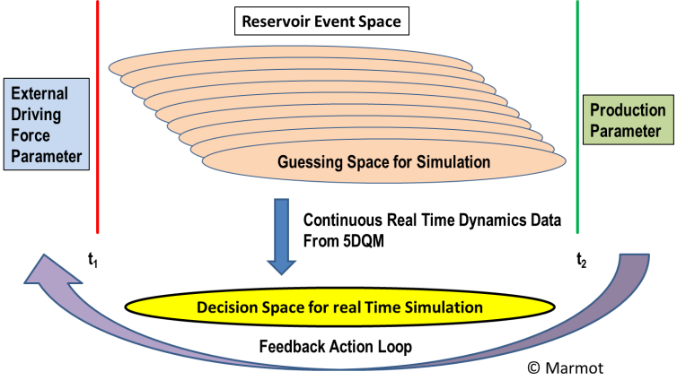
Figure 4.1 : Reservoir feedback loop reaction delay space (system time constant)
The 5DQM technology can provide the continuous far field information currently lacking in reservoir analysis and management wherein only limited point source data is available from smart well locations. Mapping the movement of fluids, as well as structural changes within the reservoir, provides for reservoir management on a previously unavailable level. When brought into the framework of a 3D geomodel[7] and compositional reservoir simulator and fully coupled with it, these tools can provide the capability of optimizing reservoir performance by optimizing production, injection and the movement of fluids through the reservoir.
While 5DQM is herein focused on conventional reservoir management application to oil and gas reservoirs, the technology has similar and related value in related applications. The ability to map and monitor both fluid and structural differentials has critical application in scenarios where structural degradation of the reservoir needs to be managed to ensure operational integrity, and the integrity of the surface above,
Figure 4.2: Information flow systematic
such as with the Groningen Gas Field in the Netherlands. Insufficiently managed water injection has not stabilized the reservoir structure and continued operations are in jeopardy. The ability to map fluid movement and associated structural changes provides a tool in which future water injection may be controlled more efficiently to stabilize and forestall any further structural collapse. Additionally, the ability to map steam and water movement 3-dimensionally within geothermal systems will also provide for more efficient management and optimization of utilization of those resources.
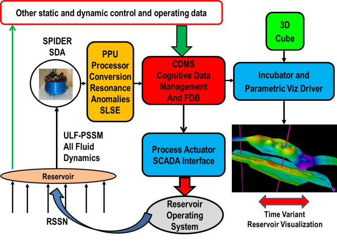
Figure 4.2: Information flow systematic
There is a large difference between Process Control (ProCon) of continuously operating technical dynamic system (TDS) like an Oil reservoir and an Enhanced Geothermal System (EGS) from which a dynamic model exists based on a reverse operation model (knowledge) – and the risk assessment of an unknown “event” which is influencing the operation environment of a technical system like an underground storage for Oil – Gas – CO2 – H2 – or nuclear waste:
Monitoring Cap Rocks and Seals and stored media dynamics in view of stochastic processes to perform a predictive risk assessment. (Some kind of Weather Forecast).
The storage facility has a technical operating system (TOS) – pumps – valves – pipes – pressure gauges: This TOS is very well defined and all action and reaction features of the technical system elements are well known and any action of such element is normally recognized by a control element and a malfunction of one of the elements is recognized as a malfunction from the operating control system.
The environment and the geological/lithological properties of such underground storages in natural formations can only be described and calculated to a certain extent in opposite to the TOS ! especially because of the influence of parameter which are NOT under control of the TOS.
Mechanistic acoustic-seismic HAZARD assessment (MASHA) is based on the assumption that no seismic event happens without a pre-history (anamnesis) and a significant acoustic-seismic footprint which can be measured and recorded as an acoustic-seismic information [12]. Continuous monitoring of the acoustic-seismic background is therefore inevitable.
The character of a HAZARD is that it is unpredictable by technical means from the TOS – otherwise it would not be a HAZARD but a malfunction.
Especially for an underground storage the HAZARD prediction is following five principles:
- You have to take it as a matter of fact that a HAZARD can happen and will happen
- You do not know how
- You do not know when
- You do not know where
- You do not know how an “Early Warning Signal” would look like
As noted earlier, the 5DQM concept is originally designed for the control of subsurface engineering processes by continuous monitoring the acoustic-seismic background. The information required is generated by the Cognitive Data Management System (CDMS) which is inherent part of the 5DQM System.
The information to generate a control action can be derived from 3 different signal levels, acquired near surface by the SPIDER unit (Figure 3.2)
- LEVEL 1 : Seismic signals measured at the surface as induced seismicity (Figure 5.1).
- LEVEL 2 : Seismic signals (Trigger) – measured at the surface as micro displacement (off-set) without having initialized any induced seismicity and only measurable as SLSE in the spectra of the background noise (Figure 13).
- LEVEL 3 : Changes in in the spectra of the background noise (Figure 5/9) – without level 1 and 2 signals being triggered.
Figure 5.1: Time series Waveform of a seismic signal indicating induced seismicity – Level 1

Figure 5.1: Time series Waveform of a seismic signal indicating induced seismicity – Level 1
LEVEL 1 gives an information about an (induced) seismic activity – which already has happened
LEVEL 2 gives an information about a “stress situation” in the rock matrix, which does not necessarily cause an induced seismic event, but may possibly act as a trigger.
LEVEL 3 indicates a change in transfer function exhibiting changes in the spectral composition of the background noise, prior to or distinctly apart from any SLSE or effect of induced seismicity appears.
Any seismic event has a measurable “anamnesis” or prehistory.
The events in LEVEL 1 are at least announced by the signals from LEVEL 2.
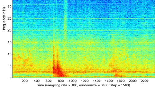
Figure 5.2.: Level 2 event
The events in LEVEL 2 are spontaneous, but may be announced by the signals from LEVEL 3.
Figure 5.2.: Level 2 event
In general, the information retrieved from LEVEL 3 signals are describing the physical state of the system under control, or changes in the physical state which are recognized and
described by the CDMS and are NOT recognized as seismic events by LEVEL 1 or LEVEL 2 signal generated information. All three level information sets and the dynamic content of the FDB are processed by the CDMS to generate a feedback action parameter for the Process Actuator (Figure 4.2)
The 5DQM Monitoring System in a producing reservoir has the task to enhance production and control fluid dynamics.
The 5DQM Monitoring System in an underground storage as a HAZARD assessment and Early Warning tool has the main task to avoid or at least minimize collateral damages of the environment and the TOS so that operation of the systems remains under control.
The 5DQM as a storage monitoring tool has only a very sparse knowledge about the event it is looking for because the “unpredictable” has no model !!
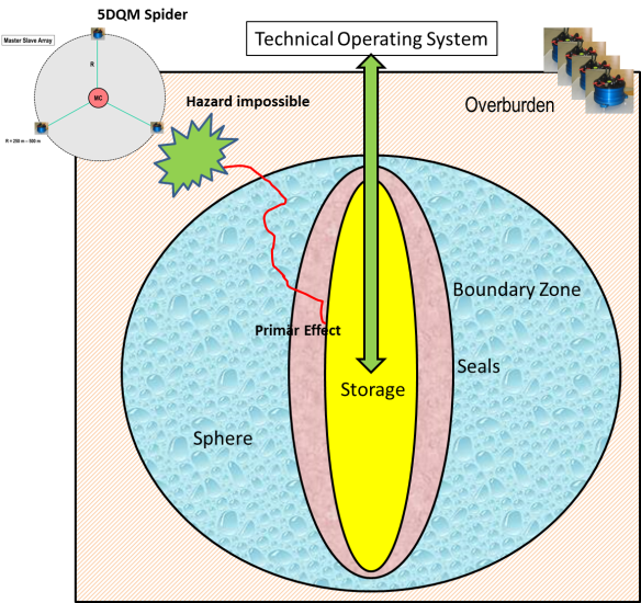
Figure 5.3.: Cavern Storage Monitoring System
The entire “Knowledge” of the system refers to the “NORMAL” behavior of the TOS and the storage environment. The CDMS learns from the very beginning the “NORMAL” behavior of the system and has the ability to recognize the deviation from “NORMAL”.
© Marmot 2019-SM/PR
App.1: Definitions and Abbreviations
5DQM 5-Dimensional Quantum Monitor
AGENT Intelligent Operating Center
AI Artificial Intelligence
ANN Artficial Neural Network
CDMS Cognitive Data Management System
DL Deep Learning
CNN Convolutional Neural Network
DLS Deep Learning Systems
FDB Forensic Data Base (Kolmogorov “Event Space” defined as σ-Algebra)
FDB stores Knowledge
MASHA Mechanistic Acoustic-Seismic Hazard Assessment
ML Machine Learning
ProCon Process Control – deterministic-numeric control of a “Technical Dynamic System”
QRT Quantification of Relation between Things
TDS Technical Dynamic System
TOS Technical Operating System
SLSE Short Life Single action Event
Perception The organization of sensory information
Knowledge The stored information acquired by a (neural) network from its environment through a learning process and used to respond to the outside world
App.2: Bibliography:
[1] Russel, Stuart J. and Norvig, Peter [2010]: Artificial Intelligence – Third Edition, Prentice Hall – ISBN-13 978-0-13-604259-4
[2] MacFarlane, A.G.J., [1964]: “Engineering System Analysis”
[3] Katok-Hasselblatt: Introduction to the modern theory of dynamical systems, Cambridge University Press, Cambridge, 1995, ISBN 0-521-34187-6
[4] Shannon, Claude E. “A Mathematical Theory of Communication“. Bell SystemTechnicalJournal.27(3): 379–423.
[5] W. Rupprecht: Einführung in die Theorie der kognitiven Kommunikation
[6] Norbert Wiener “The scientific study of control and communication in the animal and the machine.” (1948 MIT Press) ISBN 978-0-262-73009-9
[7] Uwe Lämmel, Jürgen Cleve „Künstliche Intelligenz“ – 2012 C. Hanser ISBN – 978-3-446-42758-7
[8] Ralph D. Hippenstiel “Detection Theory” – 2002 CRC Press ISBN – 0-8493-0434-2
[9] Simon Haykin “Neural Networks and Learning Machines”, 2009- Prentice Hall ISBN-13: 978-0-13-147139-9
[10] Simon Haykin “Cognitive Dynamic Systems: RADAR, Control and Radio” , Proceedings of the IEEE – Vol. 100, No.7, July 2012.
[11] Marmot MT: 2019-03-11.11 MTB Monitoring Handbook V.26 – (Chapter #2) (Internal Documentation)
[12] Marmot MT: 2017-08-15.13 MT-Geodynamic Phenomena SMRI V.18 – (Chapter #4) (SMRI Conference Paper 2017)
[13] Terrence J. Sejnowski “The Deep Learning Revolution” MIT Press 2018 ISBN-9780262038034
[14] Marmot US Pat. 7,365,410 B2
[15] Michael J. Bianco, Peter Gerstoft et. al. : “Machine Learning in Acoustics: A review” – Research Gate
[1] Kolmogorov / McFarlane
[2] Shannon, Claude E. “A Mathematical Theory of Communication”
[3] Terrence Sejnowski „The Deep Learning Rovolution“ (MIT Press 2018)
[4] Haykin, Simon . „Neural Networks and Learning Machines“
[5] Kolmogorov σ-Algebra
[6] A.N. Kolmogorov
[7] US Pat. 7,365,410 B2
